Senior Automation Engineer and Freelance Writer But I thought showing a more complex system was a good way to demonstrate the flexibility, intuitive setup, and ability of having the multiple devices set up in the same configuration window. This is a little more advanced than just starting with a typical PLC and HMI that would connect quickly, easily, and somewhat seamless.
#GX WORKS 2 LOCAL DEVICE STATUS SERIAL#
Once set, the next step is to get these parameters downloaded to the processor, and I'll cover those steps in detail in my next article.Īuthor's Note: The PLC in the above application connects through a lightly managed switch to a Serial Controlled Unit (via a Moxa Nport Ethernet to Serial server), an Ethernet Controlled Camera (Vision) System, and an HMI.

Figure 5, “Close with Reflecting the Setting.” Image by Paul Hunt

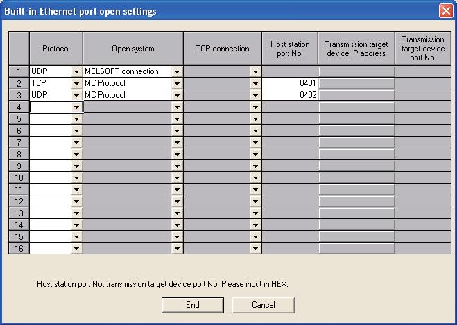
When complete, be sure you press the button on the top of the window that says to “Close with Reflecting the Setting” or else the settings will be lost. Next, step through each of the white fields at the top and enter in all of the required parameters: Figure 4 Populating Communications Config from Module List. To add your devices, you drag and drop connections from the “Module List” window on the right side of the software, and then drop them in the main config window on the left. Note: In my system above, the “Active” connection module is a Moxa Nport, the “SLMP (UDP)” connection module” is a Camera (Vision) Controller, and the “MELSOFT” connection module is an HMI. Figure 3 R-Series (left) FX5 (right.) Image by Paul Hunt In Figure 3 below you can see what these connections look like after being setup for both the FX5 (right) and the R processor (left). Then click on the “Configuration Access Button” (ellipsis, ) on the right. Figure 2 – R04 (left) and FX5 (right) Image by Paul Hunt This will be visible on the right side in the “Setting Item” window after double-clicking either the “Module Parameters” in GX Works 2, or the “Ethernet Port” in GX Works 3, as shown in Figure 2.
#GX WORKS 2 LOCAL DEVICE STATUS SOFTWARE#
Once the controller’s own IP configuration is set, you will need to access the Ethernet port parameters in the software by going to the “External Device Configuration”. In this case, I also have a camera system that works with Mitsubishi and has step-by-step guidelines to get connected that are protocol specific. Once you have your IP addresses chosen for your components, it may also be handy to have associated connection documentation (if available) that may be specific to each vendor in front of you. Image by Paul HuntĪs you can see above, there is a different look and feel between the two software packages. There are many similarities too, but I think the overall feel is much more intuitive (especially in parameter settings) in the newer GX Works 3 software. (see figure 1) Figure 1 -GX2 on Left, GX3 on Right.

Wa_cq_url: "/content/For those coming to GX Works 3 from GX Works 2 (or earlier,) finding the right area to modify the parameters is the first step. Wa_audience: "emtaudience:business/btssbusinesstechnologysolutionspecialist/developer/fpgaengineer", Wa_primarycontenttagging: "primarycontenttagging:intelfpgas/intelprogrammabledevices/intelarria/intelarria10fpgasandsocfpgas", Wa_emtcontenttype: "emtcontenttype:designanddevelopmentreference/developerguide/developeruserguide",


 0 kommentar(er)
